
How to Choose the Right Pogo Pin Charging Solution for AI Products

The core approach to selecting a Pogo Pin charging solution for AI products is: first lock down the physical constraints based on product form factor, then design the electrical and structural aspects around contact reliability. AI products are typically space-constrained and used in complex scenarios (e.g., skin contact, mobility), so you cannot look at the Pogo Pin in isolation-the pin, magnet, pad, circuit protection, and structural guidance must be selected as an integrated system.
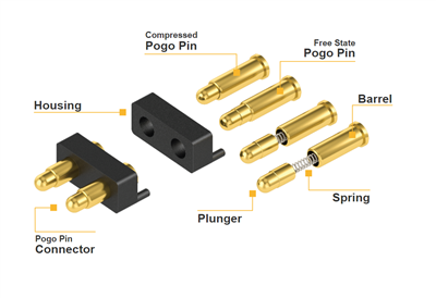
Step 1: Lock Down Key Physical Constraints Based on AI Product Form Factor
Different AI product categories have very different demands on Pogo Pins. The starting point for selection is identifying which category your product falls into.

AI Glasses / Smart Wearables (Space and Corrosion Are the Primary Conflicts)
These products have extremely thin temples or watch bodies and are constantly exposed to sweat and cosmetics. When selecting, prioritize:
Ultra-low height: Whether a mass-producible Pogo Pin with a total height of 1.25mm is available to fit the narrow stacking space in the temple.
Corrosion-resistant plating: Standard gold plating may fail within minutes under sweat/cosmetics. Confirm whether the plating can pass >168-hour salt spray/sweat testing, and whether electrolytic corrosion resistance is >60 minutes (standard gold plating is typically <1 minute).
Magnetic blind-mate tolerance: AI glasses users have difficulty precisely aligning with small holes. The solution should include magnetic assistance; the magnetic force should not be too strong to avoid impacting internal optical components, and guide chamfers should enable multi-angle blind mating.

Desktop / Home AI Devices (Ease of Use and Water Resistance Are Key)
Smart speakers, desktop robots, etc. are typically placed on a dock for charging, and users expect "drop-and-charge" convenience.
Large travel and tolerance: Pogo Pins rely on spring compression to absorb height tolerances. The dock design should let the pins carry current while the housing stop determines the final height, preventing the pin tips from bearing the device's weight.
Water resistance and appearance: If the product may contact water, ask whether the supplier offers IPX8-level solutions or special plating (e.g., Super AP) that balance charging and protection.

Step 2: Calculate Compression Using a "Tolerance Chain" Approach, Not Just Nominal Height
This is where engineering most commonly goes wrong. The compression of a Pogo Pin determines whether contact force is sufficient and whether damage will occur.
You need to calculate the worst-case combination: let H = free extension of the Pogo Pin, G = actual gap between the stop surface and the pad after assembly. Actual compression x = H − G. The key is not x in a single sample, but the x_min and x_max after all tolerances (housing, PCB, pad thickness) are stacked.

x_min too small: Insufficient contact force; slight contamination or vibration causes intermittent connection.
x_max too large: Pin tip bottoms out or exceeds working travel; long-term damage to the internal spring, or even damage to the housing.
For multi-pin arrays, also consider the left-right compression difference caused by device tilt. It is recommended to request the force-travel curve directly from the supplier and apply your tolerance chain to it, rather than judging by "feels springy enough."

Step 3: Electrical Design Must Cover "Partial Contact" Risks
The biggest fear with Pogo Pin charging is not proper insertion, but the moment when the device is not seated firmly, is placed at an angle, or foreign metal objects are present.
Positive and negative terminals not making contact simultaneously: When the device is placed at an angle, the positive terminal may contact first while the negative is still floating. Without circuit protection, an abnormal current path may occur. During selection or design, confirm whether the charging IC has input overvoltage protection (OVP) and overcurrent protection (OCP), with fast response (e.g., <1μs level) to handle inrush current at the moment of contact.

Contact resistance and heating: AI products typically draw low charging current, but degraded contact resistance causes heating and charging failure. Pay attention to the Pogo Pin's contact resistance specification (low-impedance alloys can achieve 95mΩ level, better than standard stainless steel at 113.5mΩ), and ensure the plating is wear-resistant to prevent resistance from rising after repeated insertions.
Whether data communication is needed: If the Pogo Pin also carries firmware updates or sensor data return (e.g., Omi wearable uses magnetic Pogo Pins for charging and possibly data transfer), it cannot be selected as "charging only"-signal integrity and hot-plug strategy must be reviewed.

Step 4: Write Verification Conditions into Selection Requirements
Do not just test "does it connect when properly aligned"-simulate real user behavior:
Angled placement, off-center placement, quick removal: Observe whether momentary disconnection or restart occurs.
Contact after contamination: After applying artificial sweat or sebum, is contact resistance still within an acceptable range?
Cycle life: For products like AI glasses that are plugged/unplugged daily, Pogo Pin life must far exceed conventional consumer electronics standards. Some solution providers offer Pogo Pins with over 50,000 insertion cycles; use this to evaluate long-term reliability.
An Actionable Selection Checklist: First find 2–3 Pogo Pin suppliers with experience in AI wearables or consumer electronics. Provide your complete stacking drawing, pad locations, expected compression travel, and usage environment (skin contact/sweating).

Request the force-travel curve and plating test reports for specific part numbers, then use your tolerance chain to verify that actual compression falls within the recommended range. If space is extremely thin (<1.5mm) and sweat contact is involved, prioritize solutions with mass-production cases of ultra-low height + electrolytic-resistant plating. For dock-style devices, focus on confirming whether the guiding structure and circuit protection are adequate.
